
- Scannova waste to energy concept


Thermal gasification system
This is a general description of a Downdraft Thermal Gasification system. Our DTG gasifiers range in size and capacity from a mere 10 kg/hr up to 2000 kg/hr of waste
or biomass, outputting from 10 kWe to 2000 kWe. Multiple gasifiers can be grouped together to form power platforms of any size and needs. The systems can operate 7
days per week, 365 days per year, and is energy self-sustaining and generates excess electric power that can be used for other external needs, or fed back into the
grid.
System
Our DTG systems are designed for optimal environmental benefits and have no harmful emissions:
- Water – all water used recirculates with zero discharge.
- Air – The gasifier does not release any gases to the atmosphere. Combustion in user equipment (i.e. gen-set) is much cleaner than traditional liquid fuels.
- Solid Waste – Charcoal can be used as fuel. Biological ash can be returned to the soil.
- Noise – The gasifier is practically noiseless. In case of major user equipment i.e. gen-set, nose levels are generally lower than with traditional liquid fuels.
How It All Works
The DTG process is a series of physical and chemical processes
(see Figure 2). Here is a short description of how it all works.
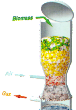
Downdraft Thermal Gasification
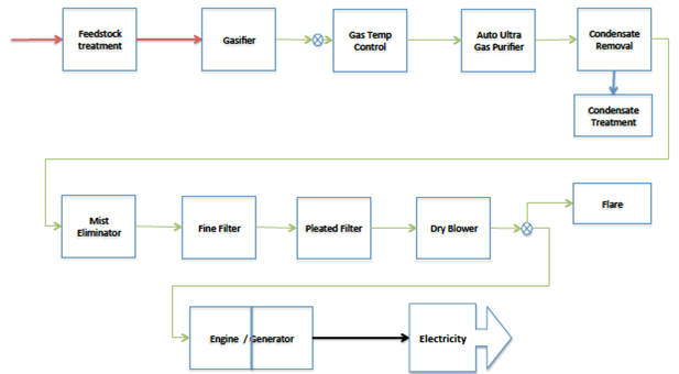
Functional flow diagram of DTG system
Feedstock preparation
Feedstock preparation is one of the most vital stages in ensuring production of
desired quality and quantity of syngas. It needs to be properly sized and relatively
dry for the gasification to be efficient. Finished feedstock is fed into the intake
hopper on the drying column of the gasifier.
Gasification
The gasifier is essentially a chemical reactor where various complex physical and chemical processes take place. Four distinct processes take place in a gasifier, namely drying of feedstock, pyrolysis, combustion, and reduction. Feedstock is fed into the gasifier at specified intervals. In the gasification process controlled quantities of air is drawn in, resulting in partial oxidation of feedstock into syngas.
Normally one kg of feedstock gets converted into 2.5 – 3.0 Nm3 of gas with a calorific value of 1000 – 1300 Kcal per Nm3. After gasification the syngas is being led into quenching and cleaning process before it is ready for final use.
Gas cooling and cleaning
After the gas exits the reactor its temperature is around 450°C or greater. The
hot gas contains almost no tar and very small amount of fine particles of ash and
soot. Depending on the application, the gas may need to be cooled to ambient
temperature, and at the same time the ash and tar (if present) need to be
handled. The system used for cooling and cleaning the syngas is explained below.
Tar cracking in the gasifier
The gasifiers have been specifically designed with proper throat size and throat
nozzle geometry to ensure almost complete tar cracking in the gasifier itself.
Thus, the hot gas leaving the gasifier is generally tar-free over the operating
range of the gasifier.
Dry gas cleaning - new developed system removing use of process water
The dry gas cleaning system essentially cools the gas using a heat exchanger.
Then the gas is passed through a fabric filter, which removes the particulates
and tars from the gas. The gas is then further cooled and passed through a
sawdust filter and a pleated filter, leaving a very clean and ready for use
syngas.
Some of the advantages of the dry gas cleaning system compared to
traditional wet filtration system are:
- No direct contact of water with gas for cooling
- Hot air generated in gas cooler can be used for drying of feedstock
- Both particulates and tar removed in fabric filter are dry and hence easier handling
- Reduction in size of fine filters
- Less space required for installation
- Low captive power required compared to wet filtration
Fine filtering system
These are sawdust filters that remove the particulates and the tars. Two or
more of these filters are used in series. The gas after these filters is almost
clean as ambient air. The sawdust used in these filters is of a certain quality
that can be re-used in the gasifier after changing.
Check filter
A pleated cartridge filter is used to ensure that coagulated particulates are arrested at this point. The gas coming out of the check filter will generally have total tar and particulate level of less than 5 mg per Nm3 of gas. This level
of cleanliness also allows our gasifiers to be easily connected to turbo charged and/ or after-cooled engines.
Electrical generation - Syngas is combusted in a gen-set to produce electricity
Different gen-sets can be used to produce electricity. Dry and cool syngas is fed
as fuel into a suitable engine, either to operate in 100% gas mode or as dual-fuel
mode with diesel.
Exhaust feedback
Exhaust coming from the gen-set can be sent to a distribution box where it is fed into the drying column of the gasifier.